Explore o6\Embedded with our
OPC UA Embedded Automation Kit
NS0 Full + DI + Encryption with <100kB RAM
Getting Started
1
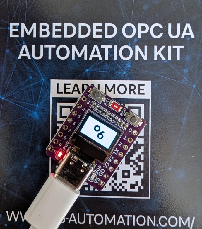
Power the Device
The Board is Pre-Flashed. Just Plug-In USB-C Cable.
2
Connect to AP
The Device automatically Open an Access Point "o6 Embedded".
3
Connect UA Client
Connect to the Device Using the OPC UA Client of your Choice. Device IP is shown on the OLED.
4
WiFi Integration
Use Methods in Objects/Network and enter your WiFi SSID and Password.
Embedded OPC UA Automation Kit Documentation
The Embedded OPC UA Automation Kit Documentation turns a ESP32-C3 Microcontroller into a fully featured OPC UA server. Out of the box, the kit provides an OPC UA server on port 4840 with full Namespace Zero and the OPC UA Device Integration (DI) and Encryption.
Nine GPIO pins are controllable via OPC UA, supporting digital input, digital output, PWM and ADC modes. Each pin's mode is switchable at runtime through a typed GpioMode enumeration. A Blink method lets you toggle the onboard LED for a configurable duration.
Live monitoring variables expose the current WiFi status, IP address, SSID and free heap memory, all readable by any OPC UA client and shown simultaneously on the integrated 0.42-inch OLED display. The device object follows the DI companion specification with Manufacturer, Model, SerialNumber, HardwareRevision, SoftwareRevision and more, making it instantly recognizable in any OPC UA client. All of this runs within roughly 95 kB of free RAM on a chip that costs a few euros- enabled by the o6\Embedded Extension.
The board connects via USB-C, which also serves as the built-in USB-JTAG interface for flashing and serial monitoring — no external programmer is needed. A 0.42-inch SSD1306 OLED display with a resolution of 72 by 40 pixels is connected over I²C on GPIO 5 (SDA) and GPIO 6 (SCL), showing the current endpoint URL, OPC UA memory usage and free RAM at a glance. The onboard LED on GPIO 8 is used by the Blink method for visual device identification. The board is powered directly over USB and creates its own WiFi network on first boot.
Flashing takes under a minute and requires only Python and a USB-C cable. The provided Kit Software Download here provides all you need. The binary files and a shell script for flashing. The file bootloader.bin is the ESP-IDF second-stage bootloader that initializes the chip hardware. The file partitions.bin defines the flash layout — an NVS partition for WiFi credentials, a PHY calibration partition, and a factory application partition. The file firmware.bin is the actual o6\Embedded application containing the OPC UA server, the ROM nodestore with Namespace Zero and the DI companion specification, the GPIO and WiFi logic, the OLED driver and the encrypted endpoint. The flash-script ties it all together: it first erases the NVS partition to clear any previously stored WiFi credentials, then writes all three binaries to their correct flash offsets in a single esptool call.
The ESP32-C3 kit is a reference implementation, but the underlying architecture of o6\Embedded is not tied to any specific chip. The key design principle is the placement of OPC UA nodes in ROM or flash memory. The entire Namespace Zero, the DI companion specification, and application-specific nodes are compiled into a compact binary that is memory-mapped at runtime with zero-copy access. This ROM nodestore approach works on virtually any embedded platform that can map a region of flash into the address space — which covers the vast majority of microcontrollers and embedded systems on the market today, from small Cortex-M devices to larger application processors running Linux or RTOS.
Because the node definitions live in ROM, the runtime RAM footprint drops dramatically. The OPC UA server only needs memory for sessions, subscriptions, and dynamic state — not for the thousands of nodes that make up a full information model. This makes it feasible to run a standards-compliant OPC UA server with encryption on hardware that costs just a few euros.
The open62541 OPC UA stack at the core of o6\Embedded already supports FreeRTOS, Zephyr, bare-metal and POSIX environments. Porting to a new platform is primarily a matter of providing a network interface and a flash mapping for the ROM nodestore binary. Use the contact form below to get more details about porting to your target platform, access to the source code examples, and the ROM nodestore generation toolchain.
Out of the box, the ESP32 creates its own open WiFi Access Point named "o6 Embedded" with no password. To integrate the device into your existing WiFi network, use the built-in OPC UA onboarding workflow.
Start by connecting your laptop or phone to the "o6 Embedded" WiFi network. Then open an OPC UA client and connect to opc.tcp://192.168.4.1:4840. Navigate to the Network folder under Objects and call the SetWifi method with two string arguments: the SSID of your WiFi network and its password.
The device stores the credentials in non-volatile storage, connects to your network as a Station, and obtains an IP address via DHCP.
The stored credentials survive reboots and power cycles. To reset the device back to AP-only mode, simply reflash the firmware using the flash script — this erases the stored credentials automatically.
Intressted in o6\Embedded?
Get insights and access to full code example.
Start with o6\Embedded now!
Full Code Access
Integration Support
Personalized Demo